سفارش تبلیغ
صبا ویژن
شکیبایی، برترین خصلت و دانش، برترین زیور و عطاست . [امام علی علیه السلام]   بازدید امروز: 0  بازدید دیروز: 1   کل بازدیدها: 9354
 
مقاله های علمی دانشجویان
 
مخابرات ماهواره ای
نویسنده: شهریار جوینده(سه شنبه 85/3/30 ساعت 1:48 عصر)
مخابرات ماهوا ره ای:


اساس مخابرات ماهواره ای به منظور دریافت تصاویر تلویزیونی بر مبنای ماهواره ایست که برنامه هایی را برای مناطقی از کره زمین( که توسط آنتنهای سطحی قابل پوشش نیست) رله مینماید. ماهواره هایی که برای این منظور به کار می آیند به طریقی در مدار خود قرار می گیرند تا همواره با سرعتی معادل سرعت زمین حرکت نموده و پیوسته بر روی نقاطی از زمین پایدار بمانند. در نتیجه این امکان را به وجود می آورد تا بتوان از آنتنهای گیرنده ای (آنتنهای بشقابی )که همواره بر روی مو قعیت خاصی مستقر شده اند استفاده نمود.


بدین ترتیب هر آنتنی که در محدوده تشعشع ماهواره قرار داشته باشد میتواند اصوات و تصاویر را با کیفیتی بالا دریافت نماید. ماهواره های متعددی به منظور مخابره برنامه های تلویزیونی در نظر گرفته شده اند. این ماهواره ها در اصطلاح به نام ماهواره های مخابرات مستقیم مطرح گردیده اند. فرستنده چنین ماهواره هایی به حدی قوی ست که تنها با بشقابک های کو چکی می توان امواج ان را به راحتی در یافت نمود.


بسیاری از کشور های اروپایی از جمله فرانسه/ آلمان در صدد برنامه ریزی جهت ارسال ماواره های مخابرات مستقیم در مدار های متفاوتی به دور زمین هستند. البته انگلستان نیز طرحهایی در این زمینه در دست داشت که به دلیل مخارج بسیار بالای آن به فراموشی سپرده شد.


تا زمانیکه ماهواره های مخابرات مستقیم هنوز به طور گسترده مورد استفاده قرار نگرفته باشند نتیجتا دست اندرکاران از ظرفیت آزاد ماهواره های مخابراتی برای مخابره برنامه های تلویزیونی استفاده می نمایند.
فرستنده های اینگو نه ماهواره ها ضعیف تر از فرستنده های ماهواره های مخابرات مستقیم می باشند. ولی با استفاده از آنتن های بشقابی بزرگتر به قطر 1.8 متر می توان از قابلیت در یافت خوبی بر خوردار شد.


در حال حاظر دو ماهواره از این نوع به منظور مخابره بر نامه های تلویزیونی برای نواحی غربی اروپا مورد استفاده می باشد. این دو ماهواره بر نامه های مخابراتی خود را بر روی 18 کانال مختلف که اکثرا به زبان انگلیسی ست ارسال می دارند. هر دو ماهواره از انواع ماهواره های مخابراتی هستند که به منظور بر قرار نمودن خطوط تلفن معمولی بین اروپا و آمریکا به کار می آیند.


اخیرا سیستم جدیدی به نام سیستم NESAT توسط کار خانه NEC طراحی و ساخته شده که مزیت کاربردی ان در این است که با اتصال آن به تلویزیون های معمولی می توان از کانال های مختلف ماهواره ای استفاده نمود. اهمیت این سیستم به علت عدم نیاز به سیم کشی جهت دریافت برنامه های ماهواره ایست.


به علاوه با کاربرد سیستم مد نظرنیاز به استفاده از سیستم های ماهوارهای مخابرات مستقیم برای بر نامه های تلویزیونی منتفی می شود. سیستم از مزایا و مشخصات میژه ای بر خوردار است که این عوامل می توانند موجب شوند تا این پدیده نوظهور به سادگی در رقابت با هر گو نه وسایل مشابهی همچنان در زمینه تغذیه بر نامه های تلویزیونی پیش تاز بوده و با استاندارد های بالای بازار های انگلیس و کل ارو پا هماهنگ بوده و مورد استقبال چشمگیر واقع شود.


سیستم NESAT از سه قسمت عمده تشکیل یافته است: آنتن بشقابی / مبدل نویز پایین و تیو نر داخلی .
البته در حال حاضر به منظور نصب سیستم نامبرده باید از مجوز قانونی بهره مند بود . لیکن پیش بینی می شود که در آینده نزدیک امکانات و ازادی بیشتری برای نصب و کاربر خانگی سیستم فوق فراهم آید.


به همین شکل بسیاری از قوانین مربوط به مخایرات تلویزونی حاضر در گذشته ای نه چندان دور محدو دیت بیشتری برای استفاده کنندگان آن اعمال می نمود و ابن در حالی بود که استفاده از مخاربرات ماهواره ای در آن لحظه خوابی بیش قلمداد نمی شد!!



نظرات دیگران ( )

Field-Effect Transistor
نویسنده: شهریار جوینده(سه شنبه 85/3/2 ساعت 2:39 عصر)


Field-Effect Transistor:
The function of Field Effect Transistors is similar to bipolar transistors (especially the type we will discuss here) but there are a few differences. They have 3 terminals as shown below. Two general types of FETs are the "N" channel and the "P" channel MOSFETs. Here we will only discuss the N channel. Actually, in this section, we"ll only be discussing the most commonly used enhancement mode N channel MOSFET (Metal Oxide Semiconductor Field Effect Transistor). Its schematic symbol is below. The arrows show how the LEGS of the actual transistor correspond to the schematic symbol.


mosfet01.gif


Current Control:
The control terminal is called the gate. Remember that the base terminal of a bipolar transistor passes a small amount of current. The gate on the FET passes virtually no current when driven with D.C. When driving the gate with high frequency pulsed D.C. or A.C. there may be a small amount of current flow. The transistor"s "turn on" (a.k.a. threshold) voltage varies from one FET to another but is approximately 3.3 volts with respect to the source.


When FETs are used in the audio output section of an amplifier, the Vgs (voltage from gate to source) is rarely higher than 3.5 volts. When FETs are used in switching power supplies, the Vgs is usually much higher (10 to 15 volts). When the gate voltage is above approximately 5 volts, it becomes more efficient (which means less voltage drop across the FET and therefore less power dissipation).


MOSFETS are commonly used because they are easier to drive in high current applications (such as the switching power supplies found in car audio amplifiers). If a bipolar transistor is used, a fraction of the collector/emitter current must flow through the base junction. In high current situations where there is significant collector/emitter current, the base current may be significant. FETs can be driven by very little current (compared to the bipolar transistors). The only current that flows from the drive circuit is the current that flows due to the capacitance. As you already know, when DC is applied to a capacitor, there is an initial surge then the current flow stops. When the gate of an FET is driven with a high frequency signal, the drive circuit essentially sees only a small value capacitor. For low to intermediate frequencies, the drive circuit has to deliver little current. At very high frequencies or when many FETs are being driven, the drive circuit must be able to deliver more current.


Note:
The gate of a MOSFET has some capacitance which means that it will hold a charge (retain voltage). If the gate voltage is not discharged, the FET will continue to conduct current. This doesn"t mean you can charge it and expect the FET to continue to conduct indefinitely but it will continue to conduct until the voltage on the gate is below the threshold voltage. You can make sure it turns off if you connect a pulldown resistor between the gate and source.


High Current Terminals:
The "controlled" terminals are called the source and the drain. These are the terminals responsible for conducting the current through the transistor.


Transistor Packages:
The MOSFETs use the same "packages" as bipolar transistors. The most common in car stereo amplifiers is currently the TO-220 package (shown above).


Transistor In Circuit:
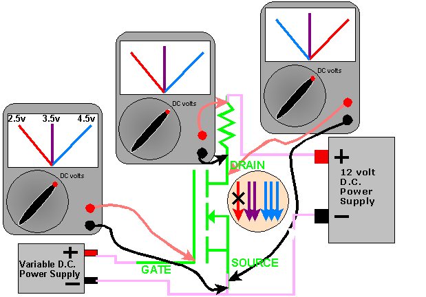
This diagram shows the voltages across the resistor and the FET with 3 different gate voltages. You should see that there is no voltage across the resistor when the gate voltage is around 2.5 volts. This means that there is no current flowing because the transistor is not turned on. When the transistor is partially turned on, there is a voltage drop (voltage) across both components. When the transistor is fully turned on (gate voltage approx. 4.5 volts), the full supply voltage is across the resistor and there is virtually no voltage drop across the transistor. This means that both terminals (source and drain) of the transistor have essentially the same voltage. When the transistor is fully turned on, the lower lead of the resistor is effectively connected to ground.
fetres.gif


Voltage applied to gate Voltage across resistor Voltage across transistor
2.5 volts no voltage approximately 12 volts
3.5 volts less than 12 volts less than 12 volts
4.5 volts approximately 12 volts virtually no voltage


In the following demo, you can see that there is an FET connected to a lamp. When the voltage is below about 3 volts, the lamp is completely off. There is no current flowing through the lamp or the FET. When you push the button, you can see that the capacitor starts to charge (indicated by the rising yellow line and by the point where the capacitor"s charging curve intersects with the white line sweeping from left to right. When the FET starts to turn on, the voltage on the drain starts to fall (indicated by the falling green line and the point where the green curve intersects with the white line). When the voltage on the gate starts to drop, the voltage across the lamp starts to increase. The more it increases, the brighter the lamp becomes. After the voltage on the gate reaches about 4 volts, you can see that the bulb is fully on (it has the full 12 volts across its terminals). There is virtually no voltage across the FET. You should notice that the FET is fully off below 3 volts and fully on after 4 volts. Any gate voltage below 3 volts has virtually no effect on the FET. Above 4 volts, there is little effect.


wmode=transparent bgcolor=#3c7c7c WIDTH=600 HEIGHT=400
TYPE="application/x-shockwave-flash"
PLUGINSPAGE="http://www.macromedia.com/shockwave/download/index.cgi?P1_Prod_Version=ShockwaveFlash">


Design Parameters


GATE VOLTAGE
As you already know, the FET is controlled by its gate voltage. For this type of MOSFET the maximum safe gate voltage is ±20 volts. If more than 20 volts is applied to the gate (referenced to the source) it will destroy the transistor. The transistor will be damaged because the voltage will arc through the insulator that separates the gate from the drain/source part of the FET.


CURRENT
As with bipolar transistors, each FET is designed to safely pass a specified amount of current. If the temperature of the FET is above 25c (approx. 77 degrees farenheit), the transistor"s "safe" current carrying capabilities will be reduced. The safe operating area (S.O.A) continues to be diminished as the temperature rises. As the temperature approaches the maximum safe operating temperature, the transistor"s current rating approaches zero.


VOLTAGE
FETs will be damaged if its specified maximum drain-source voltage is exceeded. You can obtain a data sheet from the manufacturer. The data sheet will give you all of the information you need to use it.


POWER DISSIPATION
FETs are similar to bipolar transistors as far as packages and power dissipation go, and you can follow this link back to the bipolar page for more information. Hit you"re "back" button to return.


نظرات دیگران ( )


لیست کل یادداشت های این وبلاگ
تحویل پروژه
[عناوین آرشیوشده]

|  RSS  |
| خانه |
| شناسنامه |
| پست الکترونیک |
| مدیریت وبلاگ من |

|| مطالب بایگانی شده ||
مخابرات ماهواره ای

|| اشتراک در خبرنامه ||
  || درباره من ||
مقاله های علمی دانشجویان
شهریار جوینده

|| لوگوی وبلاگ من ||
مقاله های علمی دانشجویان

|| لینک دوستان من ||
عادل حسینی
حسین رحمانی
سید محمد محمدی
پیمان والی نیا
محمد رضا صلاحی یگانه
مصطفی انوری
علی حاتمی

|| اوقات شرعی ||


|| وضعیت من در یاهو ||
یــــاهـو